
30 Apr Improved CP Anode Bed Performance
Cathodic protection (CP) anode beds are typically installed using carbonaceous backfill materials such as coal coke breeze, calcined petroleum coke breeze, or graphite particles. These carbonaceous backfills help reduce the contact resistance of the individual anodes in the anode bed by increasing the size of the anode. These backfills also increase the life of the anodes by bearing some of the current discharge. However, this requires the backfill to be in solid contact with the anodes, as inadequate contact due to soil type or operating conditions tends to reduce anode life.
Another issue with conventional coke backfill materials is that the granularity of the coke breeze particles results in less than total contact with the anode surface, which facilitates ionic current discharge from the anode surface. This current discharge leads to gas generation at the surface of the anodes, which requires venting systems to prevent gas blockage of anodes that can lead to anode bed failure. Other issues related to the granularity of coke breeze backfills include premature drying out in dry soils, as any water added to wet the anode bed tends to drain out through the porous backfill; and in cases where the borehole passes through downhole water zones, washouts and aquifer cross contamination can occur.
Over the past decade, various formulations of conductive cement backfill materials for electrical grounding applications were used experimentally as a possible solution to the granularity issues with coke breeze. These materials had a very successful operating history over decades of use in the electrical and telecommunication industries, especially where poor soil contact with the metallic grounds resulted in high resistance-to-earth values that exceeded the R values required by codes and standards, and equipment damage due to poor grounding under fault conditions.
Laboratory and Field Testing
New backfill formulations were developed, based on those with carbonaceous and graphitic materials used for electrical grounding, to address issues such as lower moisture or high salinity levels in various soil environments.
Following proof-of-concept tests in the lab, these new formulations were tested in the field. A summary of the lab and field test results is given below.
Lab Test Results
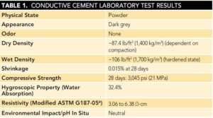
Lab testing included density, shrinkage, compressive strength, water absorption, resistivity, and pH (Table 1).
One of the first field tests was conducted in severe drought conditions in South Texas. Deep anode beds installed with carbonaceous backfills had experienced short service lives and high resistance-to-earth over the previous 35 years.
A test installation using conductive cement was installed in January 2006, with the following deep anode bed configuration:
- Anode hole diameter: 10 in (254 mm)
- Anode hole total depth: 235 ft (70.6 m)
- Active backfill column: 180 ft (54 m)
- of anodes: 15
- Anode size: 4 by 72 in (102 by 1,829 mm)
- Vent Pipe: None
The conductive cement deep anode was designed for an output of 30 A; however, during the first year of service, the output was raised to more than 70 A by the operator because the traditional anode beds in the area were progressively failing due to the dry soil conditions.
After the first year, average rectifier settings ranged from 8.40 to 8.75 V, with associated current outputs of 60.3 to 76.6 A.
The points to note regarding these field test results are:
- The original design was for an anode bed with a rated current output of 30 A direct current.
- Once the bed was energized, the current was raised in the first year of service by the operator to more than 70 A (nearly 2.5 times the designed output).
- The anode bed output current remained consistent in the 60 to 70 A range, with no indications of seasonal drift.
- The bed exhibited a significant decrease in resistance from 0.245 to 0.109 Ω in the first three years of service, with a marginal increase to 0.145 Ω after six years.
Case Studies
The following case studies illustrate the performance of anode beds installed using conductive cement backfills. These installations were either done by major oil and gas operating companies or leading CP vendors who recommended the use of the conductive cement backfill to address challenging and aggressive operating conditions.
Conductive Cement Backfill vs. Coke Breeze Backfill Comparison Test
This test was conducted by a major North American pipeline operator to compare the performance of the two backfills in similar soil conditions (a farmer’s field in Indiana).
The two deep anode beds were connected to a single rectifier. The installation specifications were:
- Two deep anode beds installed 150 ft (45 m) apart.
- Both anode holes were 50 ft (15 m) deep by 11 in (279 mm) in diameter.
- Five anodes were installed in each hole.
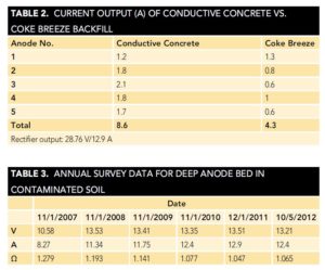
The test was started in 2010 and is still in operation to date, with average current outputs shown in Table 2.
Comparison of High-Resistance Deep Anode Beds
Rapid drying out of deep anode beds installed with conventional coke backfill was experienced by a major petroleum operator at a number of locations in Wyoming. The very dry downhole soil strata, as well as the porous nature of conventional backfill materials, contributed to the rapid drying out. In very dry soil conditions, the water in the backfill slurry dries out over time.
Conductive cement backfill anode beds were installed as replacement anode beds at the problematic locations, with 10 anodes measuring 4 in by 72 in, in a 250-ft (76-m) active column 350-ft (107-m) total depth and 10-in (254 mm) diameter.
The new installations included a provision for watering the anode beds—water could be added in the top water chamber section, which consisted of a 10-in PVC casing installed above the active backfill column, to keep the backfill column hydrated.
Only five months of operating data were available for the conventional anode bed, but it experienced a rapid increase in resistance, from 11.50 to 20.35 Ω in that time frame. Average outputs were 62.09 V and 4.79 A (13.0 Ω), while the anodes with the conductive cement backfill averaged 47.04 V and 20.74 A (2.30 Ω).
While the conductive cement anode beds performed much better, the resistance increased after the first year of operation. It is expected that once the current output drops below acceptable limits, the operator will refill the water chamber to reduce the anode bed resistance.
Conductive Cement Anode Bed in Contaminated Soil
Following issues related to hydrocarbon-contaminated soil near an oil refinery, a major West Coast pipeline operator installed a deep anode bed using conductive cement backfill to compare performance with the previous coke breeze backfill anode bed. Concerns with conventional beds included degraded performance due to hydrocarbon contamination, and the possibility of contaminants polluting nearby aquifers.
The deep anode bed was installed with 10 anodes measuring 4 by 72-in, in a 150-ft (46-m) active column 300-ft (91-m) total depth and 10-in (254 mm) diameter.
The five-year operating history of the anode bed after commissioning in 2007 is given in Table 3. The anode bed operated consistently without any problems, and the anode bed resistance-to-earth steadily declined over the first four years of operation.
Linear Mixed Metal Oxide Anode in Conductive Cement Backfill (High-Resistivity Shale)
Companies operating in the shale areas on the East Coast typically experience very high soil resistivity values (more than 20,000 Ω·cm) at the anode installation depths. This results in extremely poor performance of conventional deep anode beds with coke breeze backfill, with typical resistance-to-earth values in the range of 25 to 40 Ω.
After installing a few trial deep anode beds with conductive cement backfill and a linear mixed metal oxide (MMO) wire anode and achieving resistance-to-earth values of 1 to 5 Ω, one operator installed a total of 140 deep anode beds based on this design.
The general configuration and operating information for these deep anode beds included a total anode wire length of 300-ft centered in a 400-ft (122-m) deep hole with a 6-in (152-mm) diameter.
The anode beds were installed in 2012, and reportedly have been operating successfully since commissioning. Anode beds with coke breeze backfill ranged from 25 to 40 Ω in resistance, with current outputs of 2 to 4 A, compared to those with conductive cement backfill with resistances of 1 to 5 Ω and current outputs of 4 to 7 A.
Under-Tank CP System Using Linear Mixed Metal Oxide Anodes
Rapid anode dry-out and high resistance were experienced in the Yuma, Arizona area on an under-tank CP anode system using linear anodes installed in perforated pipes filled with coke breeze backfill. Installing a watering system to irrigate the anodes did not appreciably improve the performance.
When the opportunity arose to install a similar under-tank system at a location in California’s Mojave Desert with similar dry, high-resistivity soil conditions, linear MMO wire anodes were installed using directional drilling. The horizontally drilled holes were filled with conductive cement slurry.
This system configuration, shown in Figure 1, consists of:
- Two storage tanks to be protected
- Storage tank diameters of 50 ft (15 m)
- Linear MMO anodes, 160 ft (48 m) in length
- Five installed linear anodes
- Horizontal anode spacing of 12.5 ft (3.75 m)
- Anode installation depth of 19 ft (5.7 m)
- One profile tube (for CP potential monitoring)
- A rectifier rating of 80 V/40 A
- Soil resistivity value of 25,000 Ω·cm
The system was installed in June 2011. During the first two years of operation, performance was extremely stable. Voltages ranged from 13.30 to 15.28 V (with an average of 14.17 V); currents ranged from 20.63 to 21.23 A (with an average of 21.06 A); and resistances ranged from 0.64 to 0.74 Ω (with an average of 0.67 Ω).
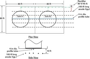
FIGURE 1: Layout of an under-tank linear MMO anode system.
Discussion
The reason for the decrease in anode bed resistance over time is attributed to the fact that conductive cement improves its contact with the surrounding soil as it cures, resulting in lower resistance-to-earth over time. Although the backfill installation is similar to the slurry pumping method for coke backfills, the conductive cement backfill cures and sets as a solid backfill column after installation. This results in a backfill column that does not allow any water to flow through it, thus preventing washouts and aquifer cross contamination in cases where the borehole passes through downhole water zones. It is important that anodes are not placed at depths where the backfill column passes through the protected aquifers. This prevents any deterioration of the solid backfill column due to anode and carbon consumption.
There is no perforated vent pipe installed in the conductive cement column, which prevents noxious gases from being released aboveground and also prevents any water flow through a vent pipe. Since the conductive cement sets as a solid around the anodes, CP current flow from the anode to the backfill is largely electronic, with ionic current flow taking place mostly at the outer surface of the solid backfill column. By managing the current density of this much larger backfill column surface compared to individual anodes in a conventional anode bed, and through correct anode bed design and operating output current control, outgassing is minimized, and any anode reaction gases are dissipated into the surrounding soil.
All three forces that dry out anode beds—electrolysis, osmotic pumping, and venting—are opposed in the conductive cement anode beds as the backfill is hygroscopic and requires no venting. This mitigates much of the issue of variations in anode bed output due to seasonal cycles. The very stable performance also shows that the bed does not lose moisture at high current output as traditional beds typically can.
Summary
The results of the lab and field tests, and data from the comparative and operational anode beds installed by major oil and gas operators and other organizations in North America, indicate that conductive cement backfills can be used successfully to overcome the challenges of extreme soil environments faced by anode bed designers and operators.
Additional environmental benefits of the solid conductive cement backfill column are the prevention of noxious gases being discharged from the anode bed, prevention of aquifer cross contamination, and prevention of damage to anode beds from pollutants in contaminated soils.
Reference:Materials Performance Guide.